How to install BFM® fitting
Watch the BFM installation videos and the read the guide below to learn how to create the correct installation gap (IG) for your BFM® spigots. Getting the right IG is essential to getting the best performance from your BFM® fittings.
MEASURING FOR THE RIGHT BFM CONNECTOR
The BFM® fitting consists of a flexible connector and two spigots.
Choosing the correct BFM® connector diameter
We recommend you use a connector with a slightly larger diameter compared to the pipe diameter above and below it.
This will minimise contact between the product flowing through and the connector wall reducing abrasion and soiling of the BFM® connector.
Choosing the connector length & Installation Gap (IG)
BFM® fitting connector lengths start at 80mm (3”), then go from 100mm (4”) through to 6m (19ft 8”) in 50mm (2”) increments.*
The length of connector you choose will largely depend on the total space (TS) you have available to install your connector.
Read more below or watch the video.
CHOOSE THE OPTIMAL INSTALLATION GAP AND LENGTH OF CONNECTOR:
To keep cost low and ensure prompt availability, try to stick to standard lengths. Our ‘standard’ connector range is identified in our pricebook as bold items.
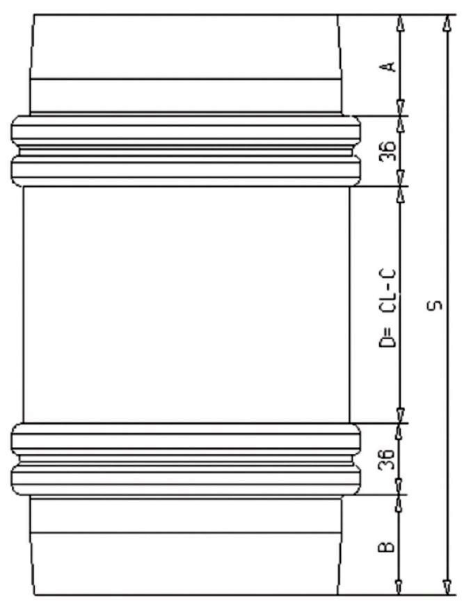
The BFM® spigots can easily be adapted to fit the existing pipework and to allow the use of standard connector lengths.
A: Length of the upper spigot tail; variable, standard
length 52 mm. May be shortened down to 10 mm.
B: Length of the lower spigot tail; variable, standard length
52 mm. May be shortened down to 10 mm.
D: Distance between both spigot ends = installation gap.
CL: Length of the flexible, transparent part of the connector.
Standard lengths e.g. 100, 150 and 200 mm.
C: Length to be added to ensure sufficient flexibility of the
connector (min. 10 mm; if the spigots are installed offset
or if large movements are to be expected, possibly
more).
S: Total distance between both pipe ends that need to be
connected.
NOTE: The installation gap always needs to be somewhat shorter than the connector length. As a general rule, mount the
spigots at a distance of approx. 10 mm less than the connector length. Example: Installation gap for a 200 mm long connector
should be 190 mm max. A connector installed too tight will be hard to be fitted in and out of the spigot; the seal may not be
100% dust tight anymore and service life will be compromised.
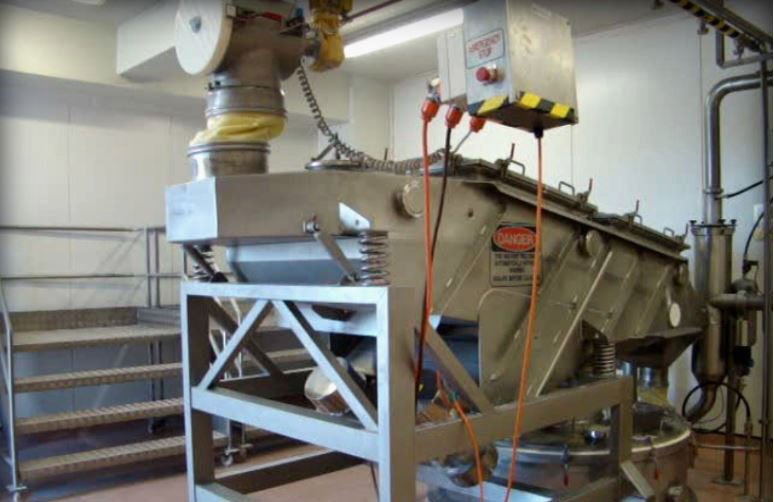
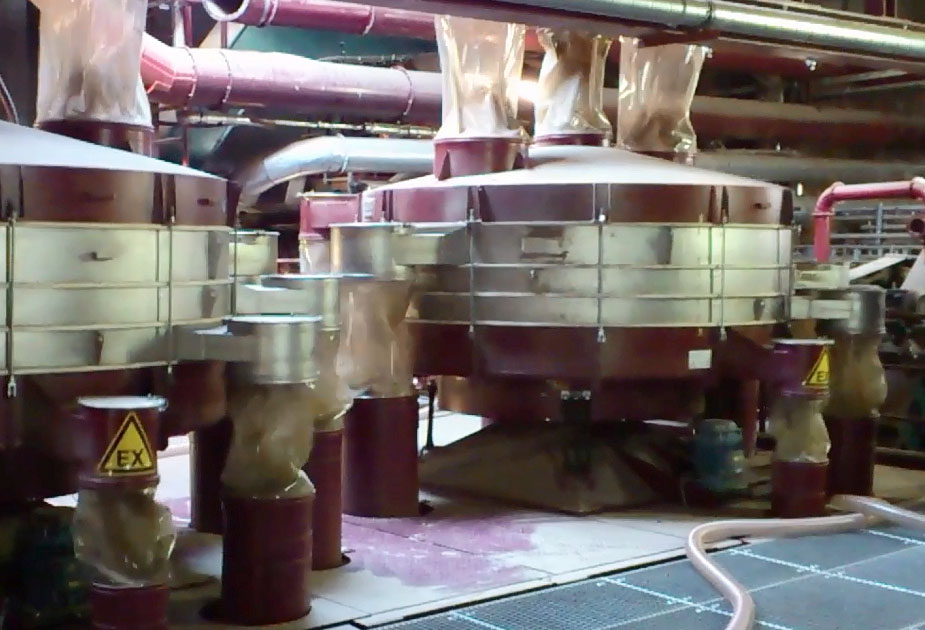
INSTALLATION GAP FOR GYRATORY EQUIPMENT:
To allow sufficient room for moving equipment, it may be necessary to choose an even smaller installation gap in relation to the
connector length.
Keep in mind, however, that excessive creasing will cause premature wear on the connector material. How much creasing any BFM® connector can tolerate, depends on:
• the diameter and length of the connector
• the type and intensity of movement
• surrounding temperature / temperature of the product
• pressure / vacuum inside the system
• chemical stress on the material due to the nature of the product being processed
Due to the enourmous diversity of processing equipment and individual manufacturing situations in themarket, it is unwise to
give exact installation advice at this point. Contact us to discuss installation gap for gyratory equipment.
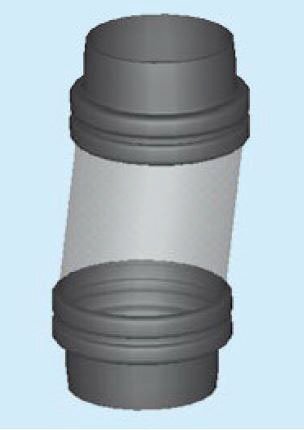
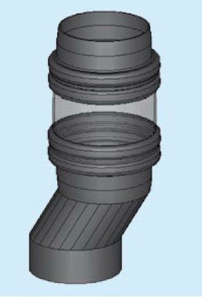
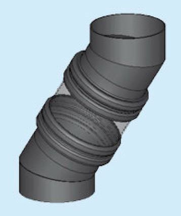
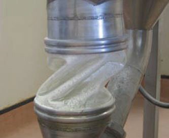
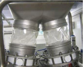
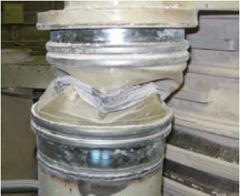
AVOID OFF-SET INSTALLATIONS:
Any off-set installation will cause increased abrasion by product constantly running along the connector wall. Also, more
pronounced off-set situations will cause the connector to crease which in turn will result in premature wear. Consider relocating
your duct work to enable an in-line installation of the BFM® fitting (see image below in the middle). If this is not possible, try to
weld on the spigots at an angle to avoid folds in the connector material (see image below to the right).